555 timer Integrated Circuit
555 Timer IC
Complete Guide to the Most Popular Timer Circuit
What is 555 Timer IC?
The 555 timer IC is a widely used and highly reliable integrated circuit in the field of electronics. It is commonly used to produce accurate time delays, pulse generation, and oscillations. Whether you're building simple LED blinkers or more complex timing circuits, the 555 timer is an essential component. It was designed by Hans Camenzind and introduced by Signetics Corporation in 1971. Since then, it has become a fundamental building block for hobbyists, students, and professionals.
Why it is called 555 Timer IC?

The name "555" comes from the three 5k ohm resistors used inside the IC, forming a voltage divider network. These resistors play a crucial role in determining the reference voltage levels used by the internal comparators.
555 Timer IC Circuit Diagram
Internal Circuit

Pin Diagram

This is the pin diagram of the 555 timer IC. It follows an 8-pin Dual In-line Package (DIP) configuration.
555 Timer IC Pin Configuration
Modes of 555 Timer IC
The 555 timer IC can operate in three main modes:
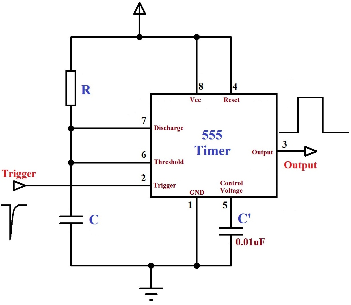
Monostable Mode 555 Timer IC
Monostable mode is a one-shot pulse mode. In this mode, the 555 timer output stays LOW until a trigger input is given. Once triggered, the output goes HIGH for a specific time period and then returns to LOW. It's useful in applications like timers, pulse generation, and switch debouncing. A common example is a doorbell – press once, and the bell rings for a specific time regardless of how long you hold the button.
Circuit Diagram of Monostable Mode 555 Timer IC

Bistable Mode 555 Timer IC
Bistable mode is similar to a flip-flop. The output stays in either a HIGH or LOW state until you press a switch to change it. It has two stable states, hence the name "bistable." This is like a toggle switch or a lamp with a push-button switch: press once to turn it ON, press again to turn it OFF.
Circuit Diagram of Bistable Mode 555 Timer IC

Astable Mode 555 Timer IC
Astable mode continuously switches the output between HIGH and LOW, without requiring any external trigger. It's often used to create blinking lights, tone generators, and clock pulses. The timing is controlled by two resistors and a capacitor.
Circuit Diagram of Astable Mode 555 Timer IC

Graph of All Modes of 555 Timer IC
Monostable Mode

Credit:- 555 Monostable | Electronics Club
Bistable Mode Graph
Astable Mode Graph

555 Timer IC Datasheet
Get the complete technical specifications and detailed information
Download DatasheetPrices of 555 Timer IC
Conclusion
Hope you found this blog informative. Feel free to comment below if you have any doubts or want a dedicated blog post on any specific mode in detail. I'd be happy to write it. Don't forget to like and share!

Comments
Post a Comment